|
Blender (jusqu'à 2.49)
|
Python:
Copy
the UV coordinates of a mesh
instead
of it's 3D coordinates
(Last
update : 21/10/2005)
|
|
Version
Française

Objective
The procedurals textures can't
be preserved in the Blender game system. However it is posssible to keep
a certain appearance passing through Vertex
colors . This method duplicate the number of vertices and weigh
down themesh object wich
becames unusable if you want to have sufficient details.
Thus this script allows to keep a trace
of all the textures assigned to a mesh,
including the uvmapped textures and the vertex colors
under
the guise of a picture that represents the unfolding of the uv coordinates
as they appear in the UVeditor window .
Method
a) Select the mesh. Switch toward
the FaceSelect mode, F key, for this operation use
the 3d window or the menu you can find in the taskbar of this window.
Define uv coordinates for your mesh (it imply that your going to use the
U
key to choose a type of projection in the menu that will appear).
b) Define the materials and textures.
c) Launch the script using the menu "Scripts/UV/Texture
Baker" you have in the Scripts window or using the menu "UVs/Texture
Baker" wich is located in the task bar of the UVeditor window.
Means
The script is based on a particularity
of the Relatives Vertex Keys .
These RVKs not only distort the geometry of the mesh
on wich they are applied but also the procedurals textures that are in
use in the mesh.
Modifiables
options
1/ re-framing
The script can partially take care of the
re-framing of the UV coordinates when these ones go beyond the limit 0.0
and 1.0. However, this imposed re-framing put the coordinates
out of phase when the farthest limits aren't the one of a square. This
fact seems to annoy the users. Thus by default this option is not activated.
If, in spite of that, someone want to try it, this person will have
to :
| New Method : in Blender 2.43 version
CVS

push the limit button,
when the dialog box appears, |
|
Old Method (up to Bender
2.42)
edit the script, find the variable named
"LIMIT"
and assign it the value 1 . |
2/ Save or not the picture
The new script lets the resulting
image in the render window but if you toggle the Replace
Img button, it will try to save if it does not exist already
a file with the same name .
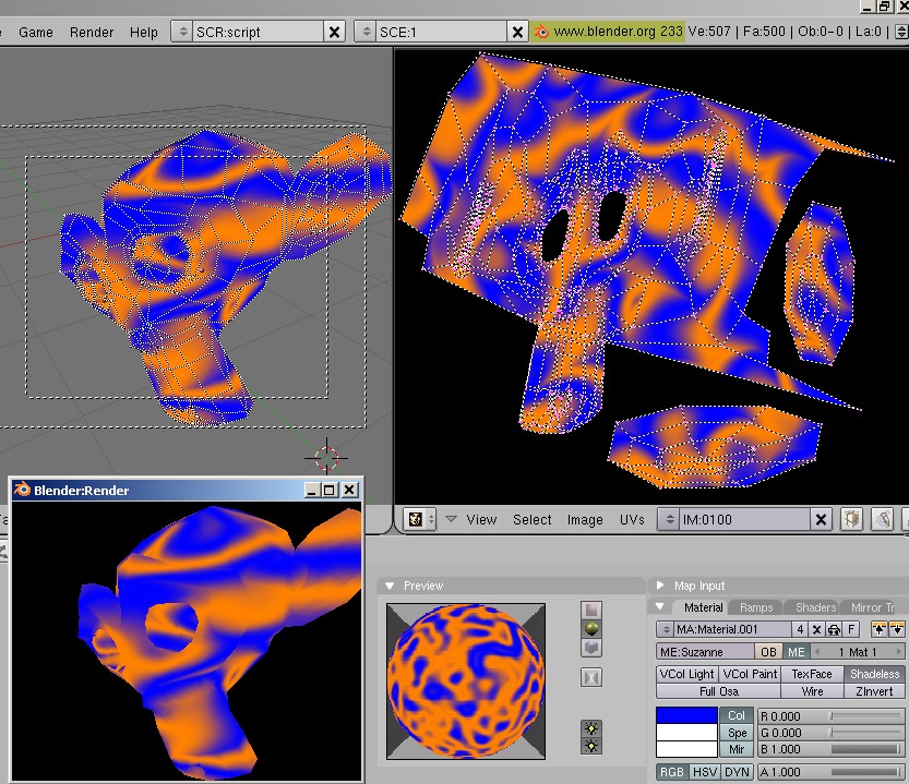
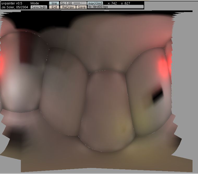
UV layout, exporting
the fill/raster of the simple uv coordinates.
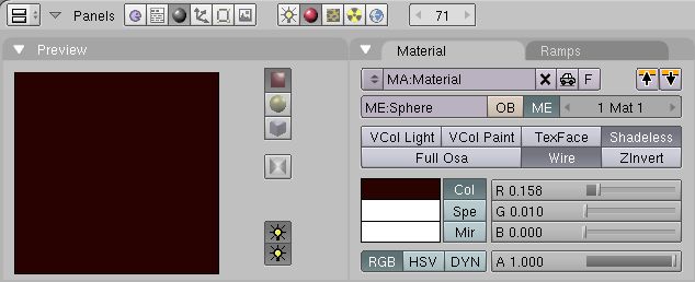
The whole trick consist in selecting
the Wire option of the material, after having prepared a color contrasting
...

(click on the picture to
zoom out)
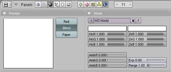
...with the background. Prepare a World
in accordance with, for example white if the color tends toward a dark
sepia.

(click on the picture to
zoom out)
Launch the script. The first dialog ask
if there is a need to change the name of the picture. Choose t No Replace
.

Choose the size :

Caution :
IMAGESIZE
By default the maximal size of
the image is limited to 2048 but if you wish to increase or modify
this value just do a text resurch on the variable TAILLEIMAGE
and
suppress the "#" .
Do not forget to do the same on the code
routine if that is placed just below .
#...
TAILLEIMAGE='TEXTURE OUT RESOLUTION : %t |'
TAILLEIMAGE+='256 %x1 |'
TAILLEIMAGE+='512 %x2 |'
TAILLEIMAGE+='768 %x3 |'
TAILLEIMAGE+='1024 %x4 |'
TAILLEIMAGE+='2048 %x5 '
#TAILLEIMAGE+='| 4096 %x6 '
tres = Draw.PupMenu(TAILLEIMAGE)
if (tres) == 1: res = 256
elif (tres) == 2: res = 512
elif (tres) == 3: res = 768
elif (tres) == 4: res = 1024
elif (tres) == 5: res = 2048
# elif (tres) == 6: res = 4096
else: res = 512
#... |
|
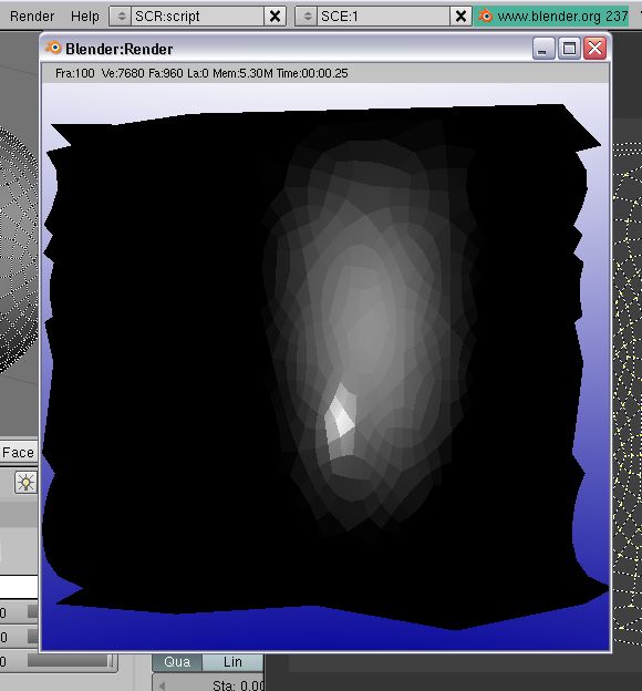
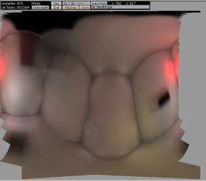
The script will do the "settings" and will
keep the "render window" displayed :

You take charge of the saving. Go to the
F10 window, Render, pannel Format :
:
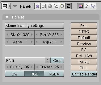
Select the format :

Push on the F3 key and record. The
image is still available for display with the short keyF11
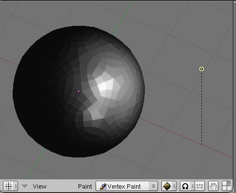
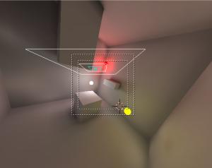
Recording
the local lighting

To obtain a copy of the local
lighting on the mesh, we can use this script :
import Blender
MESH=Blender.Object.GetSelected()[0].getData()
MESH.update(0,0,1) |
That operation has the same result
than attributing new vertex colors to the mesh .

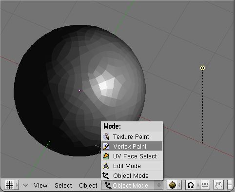
Then, we must absolutely activate
the option vcolpaint on the material assigned to this object .

Cauion
:
If the uvmapping coordinates haven't still
yet been assigned, this process can be replaced by a handly made operation
passing through the Vertex Paint mode.

(cliquez l'image pour l'agrandir)
|
We apply the UVs coordinates :

(cliquez l'image pour l'agrandir)
We launch the script :

(cliquez l'image pour l'agrandir)
Recording
a map of the radiosity
The script "Texture Baker" does
not allow to see the falling shadows of a lighting (spot
or others); But we can make appear usable shadows passing by the calculation
of a radiosity lighting, because this one works with the Vertex
colors .
1/ Classical Radio
procedure
:


-> Select a few meshes, (do not forget to assign to at least one of them,
a material with a high 'emit' value). Use the [Collect Meshes] button.

-> Launch the calculation : with the button [go] (wich has not the
color as here below)

-> button [Add new mesh], to avoid loosing the original data
-> button [free radio data], to reset all in order
2/ Put the new mesh in another layer,
touche
M, selection

3/ -> Select the new mesh, Right
Mouse Button
-> Enter the edit mode,
with the TAB key
-> Select each part
of the whole 'blocky' mesh , for example, a cube will be made of 6 separated
parts. Thus, you have to place the mouse cursor over each part, select
one of the vertex, then push Maj-RightMouseButton and use
the L key to recover the selection of all the vertices linked with
the first you have selected.
4/ When all the parts are selected.
-> do a separate,
with
the P key

-> go out of the edit mode,
with "TAB" key
-> Select the mesh
you've just created,
5/ Go to Faceselect mode,
with
F key
6/ Select all, with the A key
7/ Choose the type of unfolding,
with the
U key


(click on the picture to
zoom out)
| Caution
: The bounderies of the UVs coordinates.
According to the type of unfolding, the
uv coordinates can go beyond the standards limits. This overrun is not
annoying in itself but it will pervert the final viewing angle. The script
is not previously made to deal with this overrun, recalculate and
re-attribute correct coordinates. But it can do a correct camera viewing
angle of the whole scene without touching the original mesh, if the LIMIT
variable is equal to1.
(click on the picture to
zoom out)
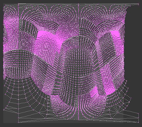
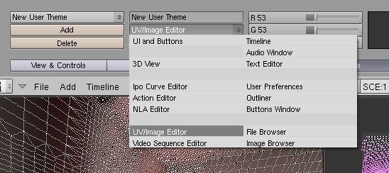
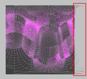
To check if the coordinates are going beyond
the limits, you need to contrast the UVmapEditor Background a bit
more, it is done by the attribution of a new Theme
in the User preferences
window
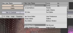
(click on the picture to
zoom out)
|
8/ Go out of the Faceselect mode,
with F key
9/ Go in the materials window ,
F5 key
-> Check if the [vcol paint]
option
is activated in the material settings.
| You could test the vertexpaint map with the the
uvpainter script click on the pictureto
zoom out but it is not obliged
|
| Caution
: List of materials and option [vCol paint]
If each of the original meshes was assigned
a different material, these materials will be gathered in the mesh produced
by the radiosity calculation . This can generate a mix-up, because the
"vertex paints" won't probably be located on the first material of the
list.
To check wich is the active material,
we can use the material index
that you can find in the edition window, in the part "Link and
Material". We must apply this procedure to each of the material :
Edit Mode
a Key to remove the selection
on the whole
Select button
a Key to remove the selection on
the whole
Go on through the list of materials
The active material should color all the vertices
in yellow . |
-> decrease the emit value
to zero (unless the emit belongs to the texture project you want
to export ).
10/ Go to the text window, shift-f11
11/ Load the last version of the
script :
http://jmsoler.free.fr/util/blenderfile/py/3d2uvbakerv034.py
12/ Do Alt-p in the text
window, choose "no replace", the size,
and so on...
Update
for version 2.40 of Blender: from absolute to relative
Since this delivery, December
23, 2005, the software does not take in charge the
absolute keys of morphing in an automatic way any more. This modification
of management poses a rather heavy problem with the script, which cannot
carry out the unfolded UV map correctly any more .
This need a short explanation : the principle
of the script consists in creating two keys: one of reference, which is
really needed to obtain a management of the texture deformation, and another,
modified, totally flat, which must be used as a model for the final shoot
. But in the new system of Shape key, the first key remains visible
because it is the one selected by default and seen by the software.
To make pass the second key ahead, one
must add an ipo curve with maximum values. The procedure is relatively
simple : one have to add a bezier knot to the coordinates at the
variable named FRAME (defined at the beginning of the script and
which corresponds to the last image calculated for animation in the currently
running file) and 1.0, which corresponds to 100% of the transformation
for this key. This manner makes it appear perfectly flat in front of the
camera.
The following function was added to carry
out these operations:
#-----------------------------------
# release : 0.3.2 , 2005/12/28 , 13h00
#-----------------------------------
def Blender240update(MESH2,FRAME):
"""
# ---------------------------
# Function Blender240update
#
# IN : MESH2 a mesh data bloc
# FRAME , the animation frame limit
#
# ADD : an ipo curve to the shape key
# named "Key 1"
#
# OUT : nothing
# ---------------------------
"""
# ---------------------------
# Get the morphing
keys for this mesh
# ---------------------------
key = MESH2.getKey()
# ---------------------------
# Try to get
the ipo
# ---------------------------
ipo = key.ipo
# ---------------------------
# if ipo
does not exist, create it
# ---------------------------
if ipo == None:
noipo = Blender.Ipo.New("Key","keyipo")
key.ipo = noipo
# ---------------------------
# shorter variable
name
# ---------------------------
ipo = key.ipo
# ---------------------------
# identify the
morphing key
# ---------------------------
keyidentity = "Key
1"
# ---------------------------
# get
the curve linked to "Key 1"
# It is always
the curve 0
# ---------------------------
ipocurve = ipo.getCurve(0)
# ---------------------------
# this curve should
not exist so we
# creates it.
# ---------------------------
if ipocurve == None:
ipocurve = ipo.addCurve(keyidentity)
# ---------------------------
# we set a linear
interpolation
# attribute to have
a real flat line
# ---------------------------
ipocurve.setInterpolation("Linear")
# ---------------------------
# we remove
all the curve's knots
# normally there
is no knot on a new
# curve but
..
# ---------------------------
while len(ipocurve.getPoints())
> 0:
ipocurve.delBezier(0)
ipocurve.recalc()
# ---------------------------
# the we add
the necessary knots...
# ---------------------------
ipocurve.addBezier((-1,1))
# ---------------------------
# ...
and this one too by security .
# ---------------------------
ipocurve.addBezier((FRAME+1,1))
#-----------------------------------
# release : 0.3.2 , 2005/12/28 , end
#----------------------------------- |
Try
the example file (7zip format, 443 kos updated with the 0.2.9 version)
Thread
on Elysiun
Changelog
0.3.3
blender 2.40
update to deal with the object module refactory
some probleme
with the relatif render directory
0.3.2
blender 2.40
update to deal with the new shape
key system .
0.3.1
stupid bug correction
0.3.0
-- adding of the variable
"TAILLEIMAGE/IMAGESIZE"
0.2.9
-- Suppression of a
test on an unused variable
0.2.8
-- added the forgotten
image
property in face data. A little longer but gives a better result.
( a Rem Double in the resulting mesh may be useful .)
-- the data.update()
function problem is corrected too
-- no more layers problem
. CAM and MESH objects are localised in layer 20. This layer
is the active one for the image rendering .
-- mesh creation
is cleaner, loop in double was removed and the absolute key is set
in frame 1 only. This solves another deform problem.
-- if user does
not want an autosaved image, the "no replace" option leaves
the render window on the screen
0.2.7
-- minor correction
on line 147: "!=-1" added
0.2.6
-- Creation of
LAMP object is removed and replaced by the use of the Shadeless
option in material object
-- helpmsg corrected
: the aim of the script is to bake any type of textures so we are
not obliged to mapinput its textures on UV .
--'pers'
camera was replaced by an 'ortho' one.
0.2.5
-- if an image
file with the same name exits the system returns an error
0.2.4
-- a LIMIT variable
is added to unlock the uvcoords autoframing
0.2.3
Great thanks for Apollux
who saw a lot of these problems
-- Everytime you run
the script a new set of objects is created. File size and memory consumption
can go pretty high if you are not aware of that. Now it ONLY creates
3 objects: a flattened mesh, a camera and a lamp.
-- all the 3 objects
was placed on layer 1, but if that layer was not visible while you
used the script all you will get a is an empty render. Now the layer
is activated before the shoot
--The flattened mesh
was really flattened only after frame 100 (if you playbacked the animation,
you can actually see the mesh becoming flat on the first 100
frames). No more.
-- When the script
is running, it changes temporary to the new camera, set the render
output to a square (i.e. 1024 x 1024 or else), does the render, and
then resets the render output and the active camera to the original one.
But if no original camera was found this produces an error.
0.2.2
If the uv mesh
object exist it is used, no creation of a new one. As well as for the lamp
and the camera
0.2.1
This script automatically
frames and shoots the new uv mesh. The image file is saved in the "/render"
directory.
Questions concerning this page can be asked
on :
news://news.zoo-logique.org/3D.Blender
|